- PowerFLARM devices
General
- What does “Error Code 41: FLARM radio” mean?
In rare circumstances, sensitive RF components can get damaged. Such a defect causes (illegal) spurious emissions of the device in licensed frequency bands, such as mobile phone bands. Such devices must be repaired.
After turning on the device, the PowerFLARM firmware automatically detects this condition. This is shown as Error 41. In the log file, typically lines as shown below appear.
WARN RF Radio A appears to be damagedERROR PFAPP *** Initialization failed: FLARM radio
At the end of the log file, the following error message is emitted once per second for 30 seconds.
INFO PFAPP Error: Severity = 2, code = 41: FLARM radio
If this error appears, the device must be repaired. Please see https://www.flarm.com/support/service-and-repair/ on how to proceed.
Always make sure to check your installation (see FTD-041).
Affected devices: PowerFLARM Core and PowerFLARM Core Pure
Introduced: PowerFLARM firmware 7.06
- Can I use PowerFLARM Fusion or Portable in an aircraft with pressurized cabin?
PowerFLARM devices contain a pressure sensor (see also What is the pressure sensor used for?), which obviously won’t produce correct readings in a pressurized cabin. PowerFLARM can still be used in these aircraft with the following provisions:
- Either
- 1090 processing is deactivated, or
- the aircraft is equipped with a Mode-S transponder. In this case, PowerFLARM will use the pressure altitude from the Mode-S signal. This is enabled by default (see below). Make sure the transponder type and aircraft address are configured correctly.
The settings in the online configurator look like this (make sure Advanced settings are shown):

- 1090 processing is deactivated, or
- The pressure altitude recorded in the IGC file will not be correct. The IGC file still contains the correct GNSS (geometric) altitude, so this is not an issue in most cases.
- Either
- What is the difference between e.g. FLAPFC10E and FLAPFC11E devices?
The digits in the part number specify the hardware version of the device.
PowerFLARM Core devices with the digits 10 imply hardware version 1.0 and do not have the option for audio out. Digits 11 imply hardware version 1.1 and have the option for audio out.
PowerFLARM Portable devices currently have digits 23 and 24. Hardware version 2.4 is an updated version with improved out-of-band filtering.
The character ‘C’ in e.g. FLAPFC11E (PowerFLARM Core) or ‘P’ in e.g. FLAPFP24E (PowerFLARM Portable) indicates that the device has a 1090 MHz receiver (SSR and ADS-B).
The last character (e.g. ‘E’ in FLAPFC11E) indicates the radio band version of the device. More information is available here.
- What is the difference between PowerFLARM Fusion and PowerFLARM Portable?
PowerFLARM Fusion is a remotely mounted box intended for installation in certified aircraft. It is installed as a Minor Change (MCA), normally behind the panel in light aircraft or in the E&E Compartment in large aircraft. The box is then connected to a FLARM Compatible display, which is installed in the instrument panel. There are also moving map systems (EFIS/MFD) that support the FLARM protocol.
PowerFLARM Portable is a portable device (PED), intended primarily to be carried by pilots who fly different aircraft which do not yet have FLARM installed. It has an integrated display and uses internal batteries and antennas. It is not primarily intended to be installed, even if an installation is also possible. It can be run on external power, in addition to the batteries.
For most aircraft, we recommend the PowerFLARM Fusion.
- Where can I buy PowerFLARM?
PowerFLARM Fusion is normally installed by an approved maintenance organization. Most maintenance organizations with avionics capabilities can install PowerFLARM.
PowerFLARM Portable is a Portable Electronic Device (PED) and normally not installed in the aircraft. It can run on batteries or be connected to an external power source. PowerFLARM Portable is sold by FLARM dealers.
Designated FLARM installers, which usually have extensive experience with FLARM installations, as well as FLARM dealers, can be found on this page.
- What is the pressure sensor used for?
The pressure sensor is used only for SSR traffic (Mode-A/C/S) and ADS-B, unless you have a Mode-S transponder, in which case it will use your Mode-S reported altitude instead. The pressure is used to compare the own altitude with the reported altitudes of other transponder and ADS-B aircraft. The pressure is also used to log the altitude in the IGC file (used by gliders). The pressure sensor can be calibrated using a calibration center, which will results in a calibration report. No calibration values are programmed in the device.
For collision avoidance with other FLARM equipped aircraft, FLARM uses only the more accurate GPS altitude difference.
- What does “Error Code 41: FLARM radio” mean?
- General use and Collision Warnings
General
- Is FLARM a poor man’s version of TCAS?
FLARM is definitely not a poor mans version of TCAS. They use different technologies and fulfill different purposes. TCAS is designed for IFR only, i.e. warns you when the ATC IFR separation minima have been, or are about to be, deceeded. TCAS cannot practically be used for VFR, since it would give you lots of annoying warnings (especially close to aerodromes, where most accidents happen). FLARM on the other hand is especially designed for VFR. It uses precise GPS positioning and flight path and collision algorithms, which would not be possible with the limited accuracy of TCAS (which is fine for IFR though).
- How many aircraft have FLARM?
As of November 2017, over 35,000 manned aircraft already have a FLARM system installed, including both the legacy Classic FLARM models and the PowerFLARM models. Most FLARM installations are in Europe. Over 50% of all GA aircraft in Europe already have FLARM and thousands of installations are currently being made each year.
In Switzerland, almost all powered airplanes and helicopters have FLARM. In the rest of Europe, most powered airplanes and helicopters have FLARM.
In Switzerland, Germany and France, all gliders have FLARM. In rest of Europe, almost all gliders have FLARM.
In the UK, over 7,000 aircraft already have FLARM, of which over 50% is powered airplanes and helicopter.
Additionally, FLARM is in use in over 20,000 drones/UAS.
- Why can’t FLARM be used for aerobatic flights?
FLARM has been designed for normal operations, including steep turns. When the aircraft is inverted (e.g. loops, rolls) or when the heading is disconnected from the 3D track (e.g. spins), the collision warning algorithms and relative bearing indications will not be reliable. FLARM should therefore not be used (i.e. turned off) during these maneuvers.
- Why can I see my own aircraft on the display?
There are two variants of this:
- An aircraft symbol is visible right at the center of the display (for moving-map-style displays) or aft (LED-style displays) with a small distance indication.
- A non-directional target is shown with small distance and/or strong signal and at the same altitude. On PowerFLARM Portable, this would show as a small circle around the ownship symbol.
In both cases, the problem is due to the PowerFLARM displaying the signal from the own transponder (Mode-C/S or ADS-B). Normally, these signals are filtered out automatically, but there are conditions under which this fails.
The following points should be verified:
- Is the 24-bit ICAO aircraft address configured correctly on PowerFLARM? In the FLARM configuration tool, the entry “ICAO 24-bit aircraft address, hexadecimal” should be verified. The address must be entered as it appears in the aircraft documents. It consists of 6 characters, 0-9 and a-f. The case does not matter.
- Is the “Transponder type” set correctly in the FLARM configuration tool?
- In some rare cases, the own transponder may be configured wrongly. On some models, the programmed ICAO address is visible at startup.
- Ensure that the “Mode-C filtering method” is set to “Aggressive”. Removing/filtering own Mode-C signals is more difficult than Mode-S or ADS-B and more aggressive algorithms may be needed.
- Furthermore, “Mode-C target processing” can be disabled altogether. This is the default setting in the configuration tool. In areas where Mode-S adoption is widespread (e.g. Europe), this is the recommended setting in any case, as the Mode-C signal is simply not needed.
If the above items do not help and it’s strictly necessary to enable Mode-C processing, it may help to move the 1090 MHz receiver antenna of PowerFLARM into line-of-sight of the own transponder antenna. If the antennas are shielded from each other, e.g. by being on different sides of the aircraft (top vs. bottom), PowerFLARM may think that it’s another aircraft because the signal is too weak. Just make sure to always keep at least 30 cm between the antennas.
Finally, note that the “1090 antenna calibration value” setting does not have any effect on the filtering. This setting only affects the calculated distance to aircraft which are already not filtered out.
Also see How is non-directional (transponder) traffic treated?
- Why do I receive collision warnings (traffic advisories) very late?
The big benefit with FLARM is that it only generates warnings when on an actual collision course, and if the collision is going to happen within the next 18 seconds. If you are close to another aircraft but not on a collision course, you will not get a collision warning. If you later turn to a collision course, you will then get a warning, possibly at a close distance.
If you get very late warnings even when on a collision course, this could be due to an incorrect (antenna) installation. Make sure that the installation is done by licensed Part-66 certifying staff. Further information about installation requirement can be found here:
- The Section Safety Equipment Requires Care and Maintenance on the Downloads page
- Document FTD-041 Application Note FLARM Antenna Installation
- Document FTD-9-65 Installation instructions, part of the EASA Minor Change Approval
In addition, the receive range of a FLARM installation can be tested with the online range analyzer.
- Is FLARM a poor man’s version of TCAS?
- ADS-B and transponders
1090 MHz Receiver
- How is non-directional (transponder) traffic treated?
Except for ADS-B, traffic received on 1090 MHz (Mode-C/S transponder equipped aircraft) is non-directional. This means that these aircraft only send a coded signal (squawk code, altitude, etc.) but not their position. Based on the power of the received signal (signal strength), as well as changes of the signal strength, an approximate distance to the aircraft and coarse collision risk can be calculated by the FLARM algorithms. However, the relative bearing to the aircraft cannot be shown, since this is not known.
Certified FLARM Compatible displays will indicate the distance and angle (or altitude difference) to non-directional aircraft. On LCD-based displays, the distance is usually visualized with a distance ring around ownship. LED-based displays show a specific LED pattern, to distinguish the warning from directional (FLARM and ADS-B Out) targets.
Displays connected using the Garmin TIS protocol cannot indicate non-directional targets. The FLARM device will instead simulate these targets by transmitting 8 ghost targets around ownship, at the approximate calculated distance. This is done on a best-effort bases, without any guarantees. Also note that it is insufficient to connect a FLARM device to a displays via the Garmin TIS protocol. As a primary means of collision avoidance, the FLARM device must be connected to a certified FLARM Compatible displays (as explained here).
- Will FLARM see all ADS-B Out-equipped aircraft?
PowerFLARM devices with an integrated 1090 MHz receiver will process all ADS-B Out (1090ES) messages, irrespective of the SIL, SDA, NIC, etc. parameters. The collision warning algorithm then calculates a collision risk and issues warnings based on the available data. This also takes into account the fact that ADS-B Out normally has lower accuracy than FLARM, e.g. by assigning higher margins.
In the US, PowerFLARM Fusion (and PowerFLARM Core with an optional feature license) can also receive ADS-R, i.e. UAT Out-equipped aircraft (see this page for limitations), also irrespective of the quality parameters. TIS-B can be received as well, but TIS-B traffic (transponder-only aircraft) have significantly lower accuracy.
ADS-B Out
- Can I use FLARM as the GPS source for my Mode-S transponder/ADS-B Out?
The GPS source in FLARM does not have any aviation certification. However, you can use a non-certified GPS source in most countries in aircraft with MTOM <= 5.700 kg. The transponder/ADS-B Out equipment must then be programmed with the required integrity setting and other parameters. Contact your maintenance organization for details.
Also note that the GPS used in FLARM has much higher accuracy and precision than aviation certified GPS sensors. Aviation certification of GPS is focused on integrity and error reporting, not accuracy (the purpose is separation and navigation, where the required accuracy is in the order of magnitude of hundreds of meters or several nautical miles). Most aviation certified GPS sources do not have the required accuracy and precision for VFR collision avoidance purposes.
- Can I use FLARM as a mandated or approved ADS-B Out equipment?
There are two different types of ADS-B, namely 1090ES and UAT.
In Europe, EASA requirements concern only 1090ES. Aircraft with MTOM over 5.700 kg are required to have 1090ES, but may in addition have FLARM. For light aircraft, FLARM is sufficient.
In the US, all powered aircraft need either 1090ES or UAT from year 2020, but may additionally have FLARM.
FLARM should however not be mixed up with ADS-B. The purpose of ADS-B is only to relieve the crowded 1090 MHz frequency and to give ATC more accurate data for separation purposes. FLARM is a collision avoidance technology similar to TCAS, but technically superior and more affordable than TCAS. Even if many FLARM devices also receive transponder and ADS-B Out traffic, ADS-B has limitations for collision avoidance. FLARM uses its own frequency and radio protocol, optimized for collision avoidance.
- How is non-directional (transponder) traffic treated?
- Obstacle collision warning system
Databases
- How do I remove the obstacle database from the device?
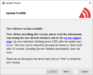
Obstacle databases have an expiration date, after which the device starts to issue errors at startup. The errors are not permanent, so the device is functioning normally afterward, but this can still be annoying if the database is not needed in the first place. Removing the database also increases capacity for (IGC) flight recording on Classic devices.
The process for removing the database for good is slightly different for either Classic or PowerFLARM-based devices. If you are unsure about which technology your device contains, our Product Finder may be of help.
Both cases require the application of a configuration file. You can use our online Configuration Tool, or download a pre-built file from below. Applying the configuration file may be a bit different depending on your device, please check the manuals.
CLASSIC FLARM
In Classic, memory is shared between the obstacle database and flight recording. Removing the database hence roughly doubles the space that is available for flight recording. However, clearing the obstacle database also deletes all flight records! So make sure to download the logs before proceeding.
In the configuration tool, the following item must be set to “Yes”. The checkbox “Show advanced settings” must be enabled for this to be visible.
Alternatively, you can simply use the dedicated file below which only clears the memory, but leaves other configuration items intact.
POWERFLARM
On PowerFLARM devices, it is possible to erase the obstacles independently of the IGC flight records. The item to enable in the web configurator is shown below. Again, the “Show advanced settings” checkbox needs to be checked for this to be visible.
We have also prepared a dedicated configuration file below that deletes the database, not modifying anything else.
- How long is an obstacle database license valid?
Obstacle databases are sold in combination with a license and published once or twice per year. They are valid until the expiration date specified on the applicable webshop page, which is around one year from when they were published. The expiration date of the installed obstacle database is also shown on the connected FLARM Compatible display.
Latest on the expiration date, the obstacle database has to be renewed by purchasing a new obstacle database license in the webshop.
For larger customers, we are also offering obstacle database updates every 2 or 4 weeks according to the AIRAC-system.
- Where can I purchase the obstacle database?
Obstacle databases can be purchased here.
- Why can’t I install the purchased obstacle database?
Each individual obstacle file (.ob2) is a combined obstacle database and license key. The license key ties the obstacle database to a specific device (model and serial number). If you try to install the obstacle database in another device, you will get an error.
If you have an avionics system with an integrated FLARM, note that the serial number to use when purchasing the obstacle database is the internal FLARM serial number, as clearly stated on the obstacle database purchase page. You should not enter the serial number of the avionics system. In some cases, the avionics system uses a similar serial number as the internal FLARM serial number. You can normally access the internal FLARM serial number under a configuration or information menu.
Warnings
- Why don’t I get an obstacle warning when flying towards an obstacle?
This could have different reasons:
- There is no obstacle database installed. Obstacle databases need to be updated at least annually and can be purchased here.
- The obstacle database has expired. Use the link above to purchase an update.
- Obstacle warnings are only issued when flying directly towards or parallel to an obstacle, at a level below the top of the obstacle (with some margin). No warnings are given in turns, if the future track does not intersect the obstacle.
- You are outside the current database area.
- The obstacle is not in the database. Only man-made fixed obstacles with a certain minimum height (depending on obstacle source, obstacle type, and geographic area) are in the database. You can see all obstacles which are available in the current obstacle database, from the respective obstacle page in the webshop.
- The FLARM display does not correctly process obstacle warnings and/or audio out from the FLARM system is not correctly installed.
- How do I remove the obstacle database from the device?
- Flight Tracking & Privacy
Flight Tracking
- I cannot register my aircraft in OGN / my aircraft shows withe wrong registration in OGN
OGN uses the DDB ( wiki.glidernet.org/ddb) to look up aircraft registrations from FLARM addresses. DDB is run by the community, please contact contact@glidernet.org to have this resolved.
- My glider is already registered in flarmnet.org! How can I get it deleted?
Please contact info@flarm.com to get the entry deleted.
Sending along a recent IGC file recorded by the FLARM device in question greatly helps to resolve issues with duplicate FLARM addresses quickly.
- I have lost my password for flarmnet.org, how can I get a new one?
There is a “Reset Password” link on the Login screen
- Why is my aircraft suddenly displayed with a changing address for a few minutes?
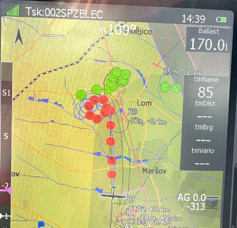
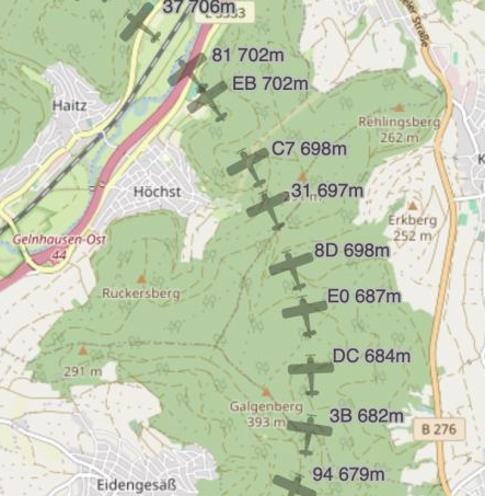
This effect occurs when a FLARM device receives a radio packet with a radio address identical to its own. For the proper functioning of the FLARM network, it is crucial that each device has its own, unique radio address. Otherwise, a receiver cannot differentiate between two transmitters. This leads to issues in visualization and collision risk calculation. To resolve this, a device automatically switches to a random address when it receives packets with a conflicting address.
The random address is renewed every 10 seconds, which results in a display like the one shown below on live tracking portals. Additionally, details such as climb rate are often removed from flight instruments. All team functions cease to work. After a maximum of 10 minutes, the device automatically reverts to using its original address.
The most common cause of a conflicting address is a configuration error: a device is configured with an incorrect address. Since 2024, there have also been reports that flight instruments based on SoftRF firmware are faulty and cause the issue by sending incorrect radio packets. An update has been available since November 2024. An alternative firmware is also available that does not exhibit this problem.
Important: SoftRF is not based on FLARM software. Correct functionality or interoperability cannot be guaranteed. Disrupting the FLARM network can negatively impact flight safety. Responsibility lies with the user.
- I cannot register my aircraft in OGN / my aircraft shows withe wrong registration in OGN
- Webshop and Customer Portal
Account
- How do I change my email address?
Your email address is used at several places in the customer portal/webshop. By design, these are not linked to each other, and need to be changed separately. Your username, which is your initial email address, however cannot be changed.
Username (email address)
Used to log in. Cannot be changed.Account email
This is the generic email address connected to your account. It is used e.g. for sending password reset emails. Change under My Account:
shop.flarm.com/shop/my-account/edit-account/Note: Do not enter or change the password when changing the account email. If you do, the email will not be changed.
Billing email
This is used e.g. for sending the invoice after each order. Change on the checkout page when making your next order or under My Account, Settings tab:
shop.flarm.com/shop/my-account/edit-address/billing/Newsletter
Cannot be changed. If required, you need to unsubscribe from the old email address and then subscribe from the new address. - How do I change my address?
To change your billing address, go to My Account on the Settings tab:
shop.flarm.com/shop/my-account/Under “Billing address”, click “Edit”.
Note that this is only the billing address used for invoices for licenses purchased in the webshop. If you are ordering devices from us, any change to the shipping address has to be communicated to us separately.
- What should I do if I have forgotten my password?
To reset your password, go to the log-in page and click the link Lost your password?
Orders / payments / invoices
- Where is the license/database/MCA that I ordered?
After completing the payment, you can download the license and obstacle files directly from the Order Completed page. You can also find the download links on the My Account page, under both the ‘Orders’ tab (ZIP file with all ordered licenses) and the ‘Devices’ tab.
When you complete an order of an MCA in the webshop, you will receive an email with the MCA and a separate email with the invoice. If paying via PayPal, you normally receive a separate email from PayPal as well.
The emails from us are sent automatically by the system the instant you complete the order. If you haven’t received one or more of the emails, they are probably in your spam folder. A few email providers (e.g. one.com) are infamous for deleting emails instead of putting them in the spam folder of the user, but there is usually a way to turn this unsatisfactory function off in the email account settings.
- Where is my invoice?
All webshop invoices can be found under the My Account page in the webshop.
Invoices are also sent to you automatically via email when you have completed the purchase. The emails from us are sent automatically by the system the instant you complete the order. If you haven’t received an email, it’s probably in your spam folder so you should check there. A few email providers (e.g. one.com) are infamous for deleting emails instead of putting them in the spam folder of the user, but there is usually a way to turn this unsatisfactory function off in the email account settings.
Licenses and Devices
- How can I delete a device from my device list?
The device list under My Account shows devices for which you have previously purchased a feature licenses or obstacle database, as well as devices that you have added manually. These devices are used to automatically populate the drop-down list when e.g. purchasing an obstacle database.
If you are no longer using a specific device, it is advisable to delete the device from your device list, so you don’t accidentally purchase an obstacle database for the wrong device. You can do this by clicking the ‘Delete’ link below the Manufacturer name in the list.

- How can I check if a feature license is installed?
PowerFLARM Core and PowerFLARM Portable can be extended with optional features by a software license. These are:
- RFB – Antenna diversity (two FLARM antennas)
- IGC – IGC approved flight recording
- ENL – Engine noise level recording (addition to IGC)
- AUD – Audio output to e.g. an audio panel
- TIS – Garmin TIS protocol
These licenses can be purchased online in the webshop. The features are activated by putting the license file on the USB stick or SD card, as described in the manual.
During installation (device is turned on with the USB/SD inserted), the connected FLARM Compatible display will show the installation progress. After installation, the installed licenses are shown in the menu of the display. See the display manual for details.
It’s also possible to check installed licenses by looking in the log files, which are written to the USB/SD during the boot process. Make sure an empty and correctly formatted (see device manual) USB stick or SD card is inserted before turning the device on. The file FLARMDEV.CSV lists installed licenses in the column starting with ‘LIC=’. Installed licenses are indicated with the number 1. The last row in the file is applicable.
- Where can I find the internal serial number?
When purchasing an obstacle database or a feature license, you need the internal serial number of the FLARM module. This can normally be found on a sticker attached on the device, or in product documentation.
When you select your device in the webshop, a help text shows you the format of the serial number for your device.
For legacy Classic FLARM-based devices from other manufacturers, the serial number is usually a three to five digit number.
In integrated devices (e.g. LX8000), the internal FLARM serial number is shown on a page in the menu. Make sure to use the internal FLARM serial number and not the serial number of the device itself. Also do not use the radio id (six alphanumeric characters).
If you cannot find the internal FLARM serial number, please contact the manufacturer of the device.
- How can I transfer a license to another account?
It’s currently not possible to move licenses between accounts. We will however implement this feature at a later time. In the meantime, if you have e.g. sold your device, you just have to give the new owner the license files with the sale of the device. License files are bound to the device, not the account, and never expire (except the obstacle databases, which habe to be renewed every year).
Devices themselves can however be added to any account, but the licenses don’t follow automatically.
- How do I change my email address?
- Installation, Certification, and Maintenance
Radio / Antennas / Range
- Does the AV-75 external FLARM antenna need a groundplane?
Yes, the AV-75 external FLARM antenna needs a groundplane to operate correctly. In most aircraft, the skin serves as the groundplane. Bonding the antenna to the conductive surface is essential. If the skin is not metal or carbon fiber, you will need a separate groundplane.
When required, a 25 cm (minimum) diameter symmetric, conductive disc mounted on the inside with the antenna mounted on the outside should be sufficient. The antenna connector and mounting hardware should run through the center of the conductive disc and make a good electrical connection to it.
The antenna installation must be done according to AC 43.13-2B Chapter 3.
Note: If the skin of the aircraft is carbon fiber, this should be sufficient as groundplane, but we suggest consulting a specialist before installation.
- How do I reset CARP – the Continuous Range Analyzer?
CARP – Continuous Analyzer of Radio Performance, automatically calculates and integrates the FLARM radio range over time.
Since CARP integrates the data without any time restriction, it has to be reset manually when needed. If the data collection period is too long, a recent degradation in the installation quality might not be visible. It’s advisable to reset CARP at least once per year, e.g. during annual maintenance, after the old CARP data (latest IGC file) has been read out and retained. CARP is normally reset using the connected FLARM Compatible display. For displays that don’t have this capability, CARP can also be reset using the Configuration Tool. To avoid reconfiguring the device, a config file that only resets CARP can also be downloaded here.
CARP is available in all PowerFLARM-based devices which have firmware version 6.80 or above.
- How can I check the range of my installation?
As explained in this article, a decent radio range is important for timely warnings and good situational awareness. Installations can deteriorate over time, e.g. the cable breaks or connectors get loose. It is thus good practice to regularly re-verify the range of every FLARM installation.
A simple and effective test is our online Range Analyzer. The analyzer requires one or multiple flight logs in the IGC file format, as recorded by the FLARM device. It uses data from received traffic for the analysis, hence it requires an abundant number of traffic encounters during the flight to generate meaningful results. Hence a log from a nice summer day with a lot of activity is better than a log from a night VFR flight
Another means to check range is the KTRAX Live Range Analyzer. The analyzer works on data received by the OGN network of receiver stations. It will thus not work if flying through areas with no OGN coverage, or if privacy options (notrack, random ID, entry in DDB) are active.
Also read our FTD-041 document on the topic.
- Can I use an antenna splitter to attach two FLARM antennas to one antenna port?
RF splitters are typically used in labs for RF measurements. They work by diverting half the power to each of two ports while transmitting, and by combining incoming RF energy while receiving.
In theory, splitters could be used to increase the coverage angle, e.g. when you have a metallic fuselage that makes it impossible to put a single antenna with good reception. However, in practice, destructive interference will normally achieve the opposite: The two signals coming from each antenna will cancel themselves out.
Therefore, it’s not permissible to use splitters. Instead, consider a device with true radio diversity, such as the PowerFLARM product line.
Find more information in FTD-041 – Application Note FLARM Antenna Installation
- What is the minimum required range for a timely warning?When flying at or below 250 kt, a range of 2 nm (3704m) forward and 1 nm to the side and behind will give the pilots a warning at least 15 seconds before closest convergence. Any range beyond that may be useful for tactical purposes but it adds very little to safety. Calculation:
- Worst case below 10 000 ft is normally two aircraft converging at 250 kt each -> 500 kt closing speed -> 257 m/s.
- For a 15 second warning -> 3858 m -> 2.08 nm
- The profile of a glider when seen from straight ahead at 2 nm distance is about as thick as a human hair held at arm’s length; almost impossible to see…
- On what frequency does FLARM operate?FLARM uses a data communication frequency in the SRD860 band or in an ISM band in different parts of the world. In e.g. Europe, the SRD860 band is used (868.2 – 868.4 MHz). In e.g. North and South America, the ISM band covering 902.2 – 927.8 MHz is used.
- Which FLARM antennas can be used?
A FLARM system is normally installed in certified aircraft. Approved antennas are usually listed in the installation instructions. For PowerFLARM Fusion, this is part of the EASA approved Minor Change (MCA). For most aircraft, the FLARM AV-75 antennas should be used for external mounting. Glassfiber gliders can also use internal antennas.
More information about antenna selection and installation can be found in the installation manual and in the document “FTD-041 Application Note FLARM Antenna Installation”, which can be found on the Downloads page.
- Where should the antennas be installed on the aircraft?
We cannot unfortunately help with specific installations, since there are so many different aircraft types. FLARM is normally installed by a Part-145 or Part-M organization, and they usually have the competency for avionics and antenna installations. Antenna placement and installation is also governed by the PowerFLARM Fusion installation manual and the EASA MCA Minor Change documents.
However, we can give some generic advice:
On most aircraft, one AV-75 FLARM antenna should be installed on top of the aircraft, and one AV-75 antenna below the aircraft. The top antenna should be placed as far forward as possible (taking the specified restrictions into account), to maximize forward range. The bottom antenna should be placed below the aircraft, on a location that ensures free view behind the aircraft. The FLARM radio signal is vertically polarized, so the antennas must be mounted vertically.
If e.g. the top antenna cannot be placed with a good forward view, it’s also possible to instead place the bottom antenna with a free view forward, and then place the top antenna to the rear. The vertical stabilizer might then obstruct the view behind the aircraft, but the bottom antenna will normally compensate for this.
Find more information in FTD-041 Application Note FLARM Antenna Installation.
Maintenance / Troubleshooting / Repairs
- When are products under warranty?
-
Products manufactured by and purchased from FLARM Technology Ltd are covered by a 6-month limited warranty (see GTC). This includes the 6 months legal guarantee in the EU (“reversal of burden of proof”), and assumes that there is no indication of incorrect installation or misuse.
For products sold in the EU, we may also consider legal guarantee repairs where the device is not older than 2 years, and the customer can demonstrate that the device was purchased new, and was correctly installed by a Part-M or Part-145 organization, or (under the supervision of) Part-66 certifying staff. To be able to consider a legal guarantee repair, a copy of the CRS and installation design documents (e.g. MCA) is required, as well as pictures of the installation covering the device, all antennas, and cabling.
-
- How do I create a support package in FLARM Hub (PowerFLARM Fusion)?
When requested by a support engineer or dealer support, you can create a support package in FLARM Hub (the PowerFLARM Fusion web interface). The package is a zip file containing configuration and debug data. The button to create the zip file can be found on the Tools / Support page in FLARM Hub. The zip file is saved on the connected computer or mobile device.
To download the support package:
- Connect to FLARM Hub. See section 3.1 in FTD-078 PowerFLARM Fusion User and Maintenance Manual.
- Go to the Tools / Support page using the navigation link in the left-side menu. If using a mobile device (narrow screen), first open the menu by using the top left menu icon (‘hamburger button’). Click on the button ‘Create Support Package’. The button functions like a guarded switch and will turn red. Click on the button again to start the package creation process.

-
The file creation process takes around 10 minutes. Do not navigate away from the page. When finished, the file will be offered for download. Save the file to the computer or device and send it to support as instructed.
The package creation takes approximately 10 minutes to complete, during which the device will be inoperable. Do not attempt this during flight.
Installation
- How can I safely operate the PowerFLARM Portable with a 24V battery?
PowerFLARM Portable accepts specified input voltages in the range of 8V to 23V. In some aircraft with a 24V battery, an alternator can elevate the supply voltage above safe levels and trigger the internal over-voltage protection. The device then goes into an error state.
In order to operate the device at a safe voltage level, a DC/DC converter must be used. Good results have been achieved with, e.g. the Val Avionics VC 760 Voltage Converter, which reduces the supply voltage from up to 28V to a safe 14V. Please follow the manufacturer’s guidelines for installation and maintenance of the voltage converter.
Other voltage convertors with similar specifications are also feasible.
- I can’t find my device in the online configuration tool.
The online configuration tool on our website only works with devices manufactured by FLARM Technology, and some devices from other OEMs. For other OEM devices, please contact the manufacturer, who can help you with the configuration.
- How long time does a FLARM installation take?This depends primarily on the individual aircraft (size, ease of access, other installed antennas, available space in and behind the instrument panel, etc.), the number of external antennas to be installed and experience with previous FLARM installations. Most installations in powered aircraft with two external antennas are completed within 16 hours, but the number of hours varies greatly depending on the factors listed above.
- What parts do I need for a common FLARM installation?
For most aircraft installations (airplanes and rotorcraft), we recommend the following:
- 1 PowerFLARM Fusion
- 1 ATD AIR Traffic Display (supplied by Air Store or their local dealer)
- 2 AV-75 external FLARM antennas for antenna diversity (top and bottom)
Most installations also require an EASA Minor Change Approval (MCA).
PowerFLARM Fusion comes with internal antennas for GPS and ADS-B/SSR. These are normally installed on the glareshield or behind the side windows. Optionally, you can also install external antennas for GPS and ADS-B/SSR, but this is not needed for most installations. Approved external antennas for GPS and ADS-B/SSR are listed in the EASA MCA.
You will also need to install antenna cables and other parts customized for the individual aircraft. Approved parts are specified in the EASA MCA.
- Who may install a FLARM system?
After installation, the aircraft must be released to service (CRS) by Part-66 certifying staff (private operation) or a Part-M or Part-145 organization (private or commercial operation) according to Part-M. Any competent person may do the installation under supervision of the certifying staff.
Certification
- What is the difference between a Standard Change and a Minor Change installation?
Installation in certified aircraft can be made either as a Standard Change or a Minor Change, depending on aircraft type and required applicability. A Standard Change installation is limited to day VFR, whereas a Minor Change allows for night and IFR). For both installation types, you need the same paperwork. It’s a common misconception that you don’t need the paperwork for a Standard Change installation — the only difference is that a Standard Change installation does not need to be approved by EASA or a DOA.
The following paperwork is normally required:
- Aircraft Flight Manual Supplement (AFMS)
- Wiring Diagram
- Instructions for Continued Airworthiness (ICA)
- Installation Instructions
- Mass and Balance Form
- Load Analysis Form
Some installers choose to create these documents themselves. Our Minor Change Approval has been created together with EASA and is already approved by them for the aircraft listed in the Approved Model List (AML); i.e. the individual installation does not need further approval. The AML for PowerFLARM Fusion includes airplanes with an MTOM up to 5,700 kg. For other aircraft, the paperwork can be used for a facilitated individual approval by EASA or by a DOA. The paperwork can also be used for a Standard Change installation.
- My aircraft is not on the EASA MCA AML. How do I install PowerFLARM?
For installation (the preferred choice for most customers, and what is recommended), you should use PowerFLARM Fusion, together with a certified FLARM Compatible display, e.g. one of the Air Traffic Displays from Air Avionics. The EASA Minor Change Approval (MCA), which you can purchase here, includes many aircraft up to 5,700 kg. For other aircraft, your installer will have to get an individual MCA from EASA. They can preferably use our MCA documents for this. To purchase the MCA for an aircraft that is not in the AML and not found in the database on the MCA product page, contact us and we will add it to the database.
If your intention is to use the PowerFLARM Portable, this is a PED (Portable Electronic Device) and does not require any installation or certification. The EASA Minor Change Approval (MCA) and the appurtenant Approved Model List (AML) is only for PowerFLARM Fusion and PowerFLARM Core.
- Is FLARM certified?
Yes, FLARM is approved by EASA for installation is certified aircraft. In light airplanes, FLARM can be installed either as a Standard Change (CS-SC051b) or as an EASA approved Minor Change (MCA) based on an Approved Model List (AML). The difference is that the Standard Change is limited to VFR day. The Minor Change does not have such limitations. Both options require an approved AFM Supplement. The MCA together with the EASA approved AFM Supplement and other required documents, for use both as a Minor Change or Standard Change installation, can be acquired here.
- Does the AV-75 external FLARM antenna need a groundplane?
- Firmware Updates & Configuration
General
- Can I run FLARM Tool on a M1 Mac?
Courtesy of Clyde Stubbs:
Updating a FLARM via serial port usually requires a Windows computer with the FLARM Tool software installed. Fortunately, the software is is written in Java, which can be ported to other architectures. Clyde has been able to repackage it with serial drivers that work on an M1 Mac.
The file is here:Instructions for use:- You will need Java 1.8 or 11.
- Plug the Flarm into your Mac M1 with a USB-serial adapter (it also needs power, 9 or 12V via the RJ45 jack)
- Note the name of the new serial port that appears in /dev e.g. /dev/cu.usbserial-2.
- Now create an empty file called FLARMDEV.CSV somewhere.
- Now run the program from a command line with `java -jar flarmtool.jar`.
- Select File/Flarm tool settings and choose the serial port.
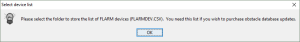
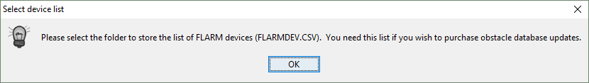
- When prompted (or by going to File/Select Device list) choose the file you created earlier.
Now you can use the firmware update, configuration and download functions. This is the latest FLARM Tool as of July 2023.
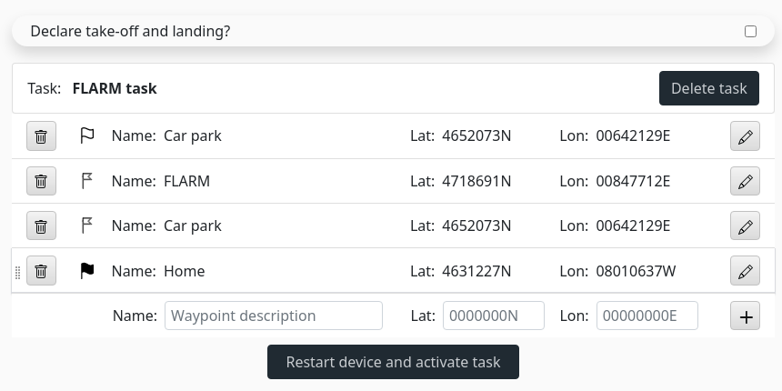
This information is provided as-is and not supported by FLARM Technology. - Workaround for invalid longitude values in „IGC Task Editor“
Applies to
FLARM Hub 1.20 to 1.22. This will be fixed in a later version.
Error description
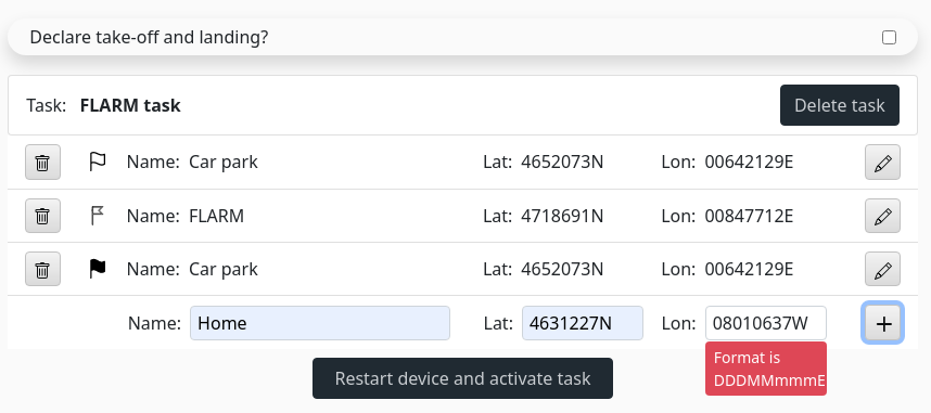
In the „IGC Task Editor, longitude values between 08000000 (W or E) and 10000000 are incorrectly flagged as invalid.
Workaround
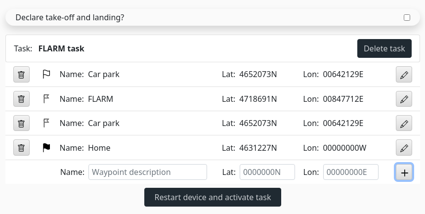
- Add your waypoint with a Longitude value of „00000000W“.
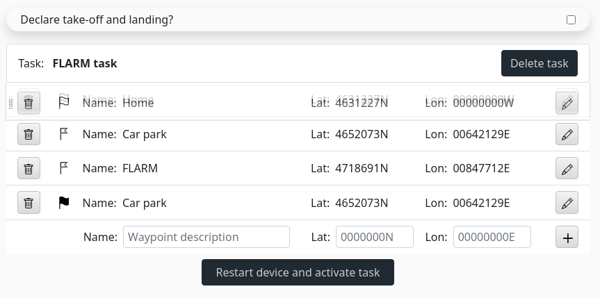
- Move the waypoint to the top by drag and dropping it.
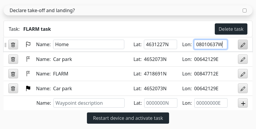
- Edit the waypoint by clicking on the „Pen“ button, change the „Longitude“ field to the desired value and end editing by clicking again on the „Pen“ button.
- Move back the waypoint to the desired position by drag and dropping it again.
-
- Add your waypoint with a Longitude value of „00000000W“.
- How does Stealth Mode work? Who should use it?
Stealth mode can be enabled using our web configurator:
This is useful only for gliders competing in a centralized competition. Other types of aircraft should not use it. Enabling it may lead to tracking services ignoring the signal.When enabled, tactically relevant flight data (such as climb rate) are hidden from competitors, such that they cannot exploit this data at large distances – which may lead to unsafe clustering of gliders.
Starting with Version 6.00, the following rules apply, based on IGC and other recommendations:
Target is more than 2km / 300m vertical away Target is closer than 2km / 300m vertical Target is nearby / collision alarm detected Target ID Not available Anonymous ID Anonymous ID Relative position Not available Available Available Relative altitude Not available Available with noise Available Climb rate Not available Not available Available Track Not available Not available Available Speed Not available Not available Available The stealth setting is symmetric: Once enabled on a device, own flight data will be shown in degraded form on receiving devices, but the own device will also only show degraded data for all received targets.
- Why is my device not listed in the online configuration tool?
The Configuration Tool on our website is primarily for devices manufactures by us, FLARM Technology. We have also included some PowerFLARM-based devices from other manufacturers, on their request. Configuration of other devices (i.e. devices from other manufacturers as well as Classic FLARM-based devices from the listed manufacturers) should be made using tools and instructions from the respective device manufacturer.
- How do I configure a device with SD card or USB port?
We recommend using the online FLARM Configuration Tool to generate a configuration file. The tool requires you to select the correct device first. If you have an account and are logged in, you can select previously configured devices.

Click „Start Configuration“ to show the configuration form for the selected device. When all items have been configured accordingly, click the „Create Config File“ button to download the configuration file.

The file must then be copied to an SD card or USB stick, as applicable for the device being configured, formatted with FAT32. Insert the card or USB stick into the device and turn it on. The configuration will be applied automatically during boot. The SD card or USB stick may not be left in the device during flight.
For details, refer to the manual of the respective device: https://www.flarm.com/en/support/downloads/
- How does the annual update cycle relate to the firmware expiration date?
In order to allow global and synchronized changes to the FLARM ecosystem, every FLARM device needs to be updated with the latest firmware version at least once per year (every 12 months). The annual firmware update must be part of the Aircraft Maintenance Program (AMP). The entry in the AMP is to be made during installation. See EASA Minor Change documents for details.
If the annual firmware update is not applied, the device may no longer be interoperable with other FLARM devices without any notification or warning.
Firmware expiry is a „last warning“ implying that the AMP has not been followed. It has also been implemented to avoid that devices that have not been updated are broadcasting obsolete data. 1 month before the firmware expiration date, the system will issue a „soft warning“ for 30 seconds, after which it will continue to operate normally. After the expiration date, the system will issue a continuous hard warning and will not operate.
The firmware expiration date is not related to the aircraft specific update cycle/date. The firmware will not expire as long as the firmware is kept up-to-date according to the AMP. The expiry is always at least 12 months plus a few months of margin in the future when downloaded from flarm.com.
For portable FLARM devices that are not part of the AMP, the owner must set up an individual reminder 12 months after the previous update.
If the annual update cycle has expired but the firmware has not yet expired, the device will in most cases continue to work until firmware expiry. - How to Recover a „Bricked“ Classic FLARM?Classic FLARM devices can be updated using our FLARM Tool Software and a data cable. If the update process is interrupted, the device may end up in an unresponsive or „bricked“ state. The firmware on the device is incomplete and can thus not be started, it remains in bootloader mode.
In this state, the device shows the characteristic bootloader LED pattern (ever 2nd LED is lit). For OEM devices, this may be different, though. Also, the device does not respond to any usual request and is not detected by FLARM Tool.
To fix the device, firmware recovery can be applied:- You need a data cable and the latest FLARM Tool software
- Leave the device unpowered / unconnected. Start FLARM Tool.
- The correct serial port must be select in FLARM Tool Settings.
- Select „Flarm -> Recover“ from the menu
- Follow the on-screen instructions

- How do I know when there is a new firmware update?
FLARM uses a rolling release cycle, requiring an annual update. Each update can be applied anytime during a rolling one year period. This makes it easier to align FLARM firmware updates with the yearly aircraft maintenance. It is also in line with the maintenance care that a safety system requires. Each firmware version is valid for at least 12 months from the date it has been downloaded, after which it will stop to function.
As the update cycle is individual, no generic information is sent out on individual firmware updates and expiration dates.
We release new firmware updates normally at least twice per year. This is however not related to the 12 months update scheme. If we do changes that affect the interoperability between devices, this will be handled automatically by the firmware, and there is no need to update the firmware outside of the 12 months firmware validity. Most firmware changes are related to special configurations or developer requests, so normally it’s advisable not to update outside the normal update scheme. - How do I Configure a Classic FLARM without an SD card slot?
A valid FLARM Tool installation is required, see this article.
When FLARM Tool has detected the device, select FLARM->Settings.
Note the dialogue has two pages / tabs. When finished, click OK to save the settings to the device. - How do I update the Firmware on a Classic FLARM without an SD card slot?
This applies to products made by FLARM Technology (FLARM04, FLARM05) as well as to certain standalone OEM products (LX navigation Red Box old version, OzFLARM). Some other non-standalone OEM products may also use this update procedure (Flytec, LX 7007), check the manuals of these products before proceeding.
A dedicated software (FLARM Tool) is provided to configure and update these devices. The following requirements are needed:- PC running Windows 7 or later operating system
- An RS-232 (serial) adapter. Typically, this is a USB to RS-232 converter. Converters using the FTDI chipset have proven to work well
- A cable connecting the RS-232 adapter with the FLARM device. These typically also provide power to the FLARM when needed, and they are available from many online sellers
FLARM Tool can be downloaded here: https://www.flarm.com/en/support/downloads/. Accept the disclaimer, then click the link „Download Flarm Tool…“ towards the end of the page. Double-click the downloaded file and follow the installer instructions. The installer also contains the FLARM firmware, so this step must be repeated whenever a new firmware is released.
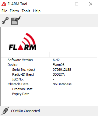
After installation, run FLARM Tool, select the correct serial port (File->FLARM Tool Settings). If unsure, it is safe to try all available ports or remove the RS-232 converter to check which port disappears (dialog window needs to be closed in between). FLARM Tool should automatically detect the connected device and indicate relevant information, see below.

- Can I run FLARM Tool on a M1 Mac?
- Flight Recording
IGC files
- What is an IGC file?An IGC file contains flight traces (recordings) of flights. It is used by glider pilots during e.g. competitions to prove records.
- How can I read an IGC file?
IGC files contain flight traces and are used primarily by gliders. The files can be read, and the flight traces visualized, using various gliding software, e.g. SeeYou. A Google search for „IGC viewer“ will show other alternatives.
- What is an IGC file?
- FLARM Hub
General
- How to verify PowerFLARM Fusion Bluetooth Connection on Android
This step-by-step guide helps to verify the PowerFLARM Fusion Bluetooth configuration on Android using the XCSoar App.
- Install XCSoar App for Android from play store in your Android device. Here is the link to the App https://play.google.com/store/apps/details?id=org.xcsoar&hl=en&gl=US
- Be sure that your Fusion device is up to date with the latest firmware releases (both PowerFLARM and Hub firmware).
- Power up your Fusion device, connect to it via Wi-Fi (we recommend to use another device such as a laptop to keep an eye on the Fusion Web Hub page). Open the section Wi-Fi & Bluetooth as shown in the following picture.
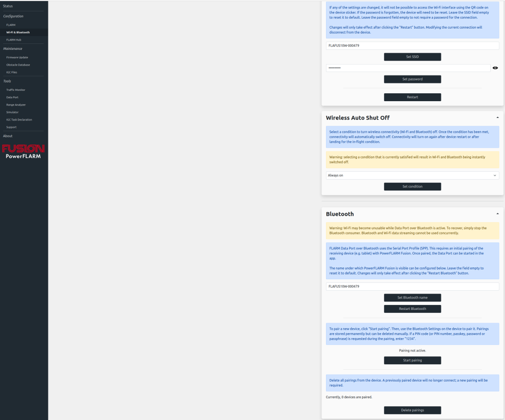
- Be sure that Fusion is not already paired: check that on the latest section of the page Currently, 0 devices are paired is shown. To be 100% sure that your PowerFLARM Fusion is not already paired, click on Delete pairings button and refresh the page using F5 on your browser. Still Currently, 0 devices are paired should be shown.
- Click the button Start pairing. At this stage, your PowerFLARM Fusion should be visible to other Bluetooth devices.
- On your Android phone, open the Bluetooth settings and select the option „Pair new device“ or similar. Be sure that your PowerFLARM Fusion device is not already stored on your device as an „already known“ device. If so, forget Fusion device through the Android Bluetooth setting.
- Once your PowerFLARM Fusion is found in the list of the new devices, click on it. At this point an Android pop-up or similar should be displayed asking if you want to pair with your PowerFLARM Fusion device. Click on Pair/Yes or similar.
- At this stage, you should be connected with PowerFLARM Fusion via Bluetooth. To verify, refresh the PowerFLARM Fusion HUB web page using F5. You should see something like this
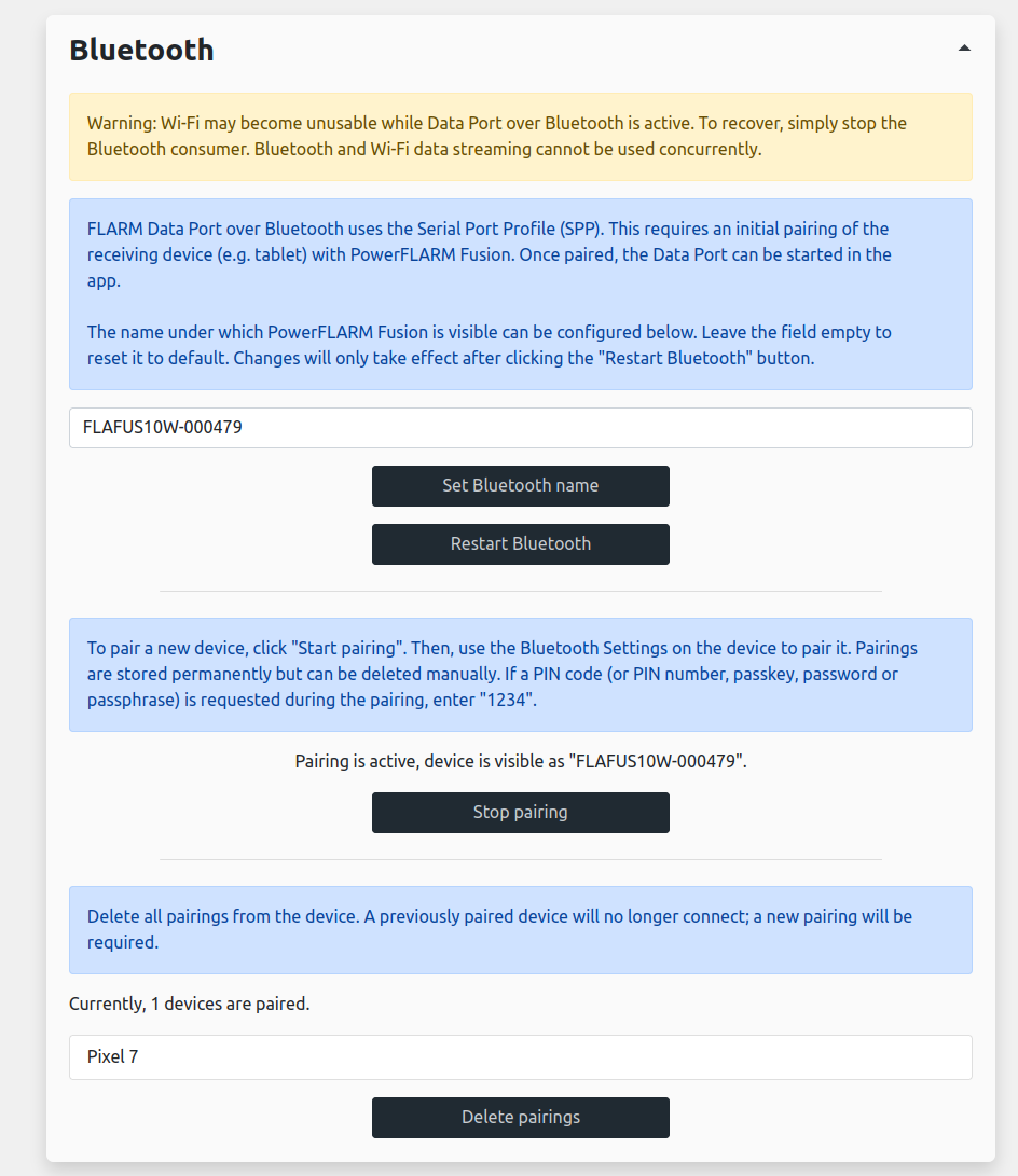
In this case, a mobile phone called Pixel 7 correctly paired with Fusion. At this point, you can press the button Stop Pairing. If, after refreshing the page you cannot see your paired device, repeat the steps starting again from the point 5. - Open the XCSoar App and perform the following steps:
- Open XCSoar App and select FLY.
- Double-Tap on the white space to open the available options.
- Select Config -> Devices to select the interface in order to receive data from.
- Select the C: Generic on Bluetooth FLAFUSXXX-XXXXXX. If this option is not available, please restart from the point 5.
- Select Monitor to retrieve the FLARM data from PowerFLARM Fusion and verify that a constant data stream is visible on this Bluetooth channel.
- Press on Close to go back to the map page. From the PowerFLARM Fusion Web Page, go to Simulator section, select FLARM aircraft and then press on Run the selected scenario button.
- You should see on the XCSoar App map page a simulated red entity coming towards the own position
- Downloading IGC files on Flarm Hub with iOS 12
With FLARM Hub on PowerFLARM Fusion, we strive to make an interface that is intuitive and easy to use on all devices. We are however sometimes limited by what your system or browser supports.
In the case of downloading files, iOS 12, which is the last version supported by older Apple devices like the iPhone 6, is limited in terms of file handling. It is not possible to simply save the file on the device, as it is the case with newer iOS versions. You can, however, save the file to your iCloud Drive, as shown below.
Step by step guide
- Connect to FLARM Hub via Wi-Fi
- Navigate to „Maintenance“ -> „IGC Files“
- Tap on „Load list of files“
- If you have IGC files on your PowerFLARM Fusion, they will appear in the list
- Tap on the file you want to download
- You should see a progress bar at the top
- Once the file is downloaded, a new window will open called blob with name „Unknown“ (it is not possible to set a file name on iOS 12)
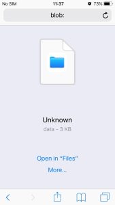
- Tap on „More…“
- Select „iCloud Drive“, then the location you want, and tap on „Add“
- Your file will be available on your iCloud account in the folder you saved it in. You can for instance open the „Files“ app, select „iCloud Drive“, and navigate to where you saved it. The file will be named „unknown“ because of iOS limitations.
Video
Below is a short video showing the steps above.
- How to verify PowerFLARM Fusion Bluetooth Connection on Android
- Displays, Integration and OEMs
FLARM Displays
- Can I connect two displays via a splitter?No, that can lead to problems and possible damage to equipment. Displays and other peripherals have bidirectional communication with the FLARM device. Connecting two displays to the same data port via a splitter can lead to incorrect data configuration and/or collision warnings not being received.
- Do I need a certified FLARM Compatible display?
Short answer: Yes, unless the display is integrated into the FLARM device (e.g. PowerFLARM Portable).
FLARM is a collision-avoidance system. Aircraft with a FLARM system alert the pilots when on a collision course with another aircraft. Similar to TCAS/TAS, visual and aural warnings indicate that a collision is imminent, requiring the pilots to take action. In addition, many FLARM systems can also show nearby aircraft on a radar-like screen (CDTI). FLARM can also warn about fixed obstacles and dynamic alert zones.
To enable tens of thousands of FLARM-equipped aircraft to communicate efficiently, the FLARM firmware needs to be updated every 12 months. The status of the system, and any error condition, is continuously communicated to the connected FLARM Compatible display.
The communication between the FLARM device and the connected display utilizes the open and freely available FLARM protocol, as defined in the FLARM ICD (document FTD-012). This ensures correct and complete communication not only of collision and other warnings but also of all status and error conditions required for the pilots to be able to verify that the system is operational.
A display that is certified as FLARM Compatible has been shown to implement all required systemic functions, both on a protocol and user interface level, as well as being in conformity with the relevant EASA Certification Specifications (SC). The FLARM Compatible Certification Specification for displays is freely available to developers (document FTD-013). The certification is free of charge.
Note: Since FLARM systems and displays do not require an (E)TSO, the certification of displays is administered outside of the EASA system. The Certification Specification for FLARM displays is not an EASA CS.

Displays that have been certified as FLARM Compatible carry the FLARM Compatible logo (see depiction on the right). A list of certified FLARM Compatible displays can be found in the Product Finder under the Category ‘Primary Displays’. Non-certified displays can be used as a secondary display e.g. for complementary traffic information. If the primary display has not been certified as FLARM Compatible, it may be possible to still use it as a primary display if the deviations are understood and the resulting risks are acceptable or mitigated. This should be done as a risk assessment as described in the device-specific Instructions for Continued Airworthiness (ICA). If not available, the generic FLARM-ICA can be used instead (document FTD-073).
Display and EFIS integrations
- Can I connect my FLARM device to a Garmin/Avidyne/etc?
FLARM devices connect to a wide range of FLARM displays, display interfaces, PDAs, on-board flight computers, moving map applications and MFDs. As a primary means of collision avoidance, a FLARM device without an integrated displays must be connected to a certified FLARM Compatible display. In addition, it’s also possible to connect a secondary display for integrated traffic information.
A FLARM device must be connected to a certified FLARM Compatible display for full safety functionality and diagnostics capabilities.
Displays which have been certified as FLARM Compatible can be either standalone or integrated in other avionics, e.g. MFDs. Certified displays carry the FLARM Compatible logo (see depiction on the right). Certification ensures that all required systemic functions have been implemented and that pilot presentation complies with aircraft certification requirements. This includes collision warnings, status information, error conditions, obstacle warnings, documentation, etc.
A list of certified FLARM Compatible displays can be found in the Product Finder under the Category ‚Primary Displays‘.
For connecting to a secondary display, some FLARM devices have the option to transmit traffic data also using the Garmin TIS protocol. This requires the FLARM data port, to which the external display is connected, to be configured for Garmin TIS. This can be done by using the online configuration tool.
Note that it’s not sufficient to only connect FLARM to a display using Garmin TIS. The FLARM data port protocol contains much more information, including collision warnings and status/error conditions, which are required for a FLARM installation. This is one of the reasons a FLARM device must be connected to a certified FLARM Compatible display using the FLARM protocol. In addition, it’s possible to also connect FLARM to a secondary display for integrated traffic information, using either the FLARM protocol or Garmin TIS. Note, however, that Garmin TIS offers only limited functionality. E.g. non-directional traffic (SSR Mode-S) may not be shown.
Several EFIS/MFD manufacturers are currently working to implement the FLARM data port protocol and to certify their displays and systems as FLARM Compatible. We recommend inquiring about the status of implementation from the system manufacturer.
More information about the requirement to use a certified FLARM Compatible display, as well as alternative means of compliance, can be found under this FAQ entry. - I’m developing a display. How can I integrate FLARM collision warnings from a connected FLARM device?
FLARM devices transmit traffic and collision data using FLARM-specific NMEA sentences over RS-232 (PFLAx sentences). The ICD and configuration specification is freely available to developers following an individual request.
If you are developing a new display or want to integrate FLARM data into an already existing display, the ICD should be used together with the FLARM Compatible Certification Specification (document FTD-013). Equipment which conforms to the certification specification can be marketed as FLARM Compatible and use the FLARM Compatible logo.
The request forms for the mentioned documents are available at the bottom of the Downloads page.
You should also note that each FLARM devices must be connected to a certified primary display, as defined in FTD-013. In additions, installers may connect FLARM devices to other (secondary) displays to e.g. show proximate traffic.
Contact us if you have any questions regarding certification.
OEM Modules
- How can I integrate FLARM into my avionics product?
We offer PowerFLARM OEM modules to make it easy to rapidly integrate full FLARM functionality into your product at a small form-factor, low weight and power (SWAP). To avoid duplication of key components, GNSS and time pulse data, power, and UI is provided externally. More information about the modules, as well as product sheets, is available on the Module page.
The OEM modules are made available to integrators under a licensing and framework agreement. A one-time license fee covers initial setup and support. The agreement gives you the right to purchase an unlimited number of OEM modules for product integration, and to use the name ‚FLARM‘ and the FLARM logo to market the product.
For more information or to sign the agreement, contact us.
- Can I connect two displays via a splitter?
- Aurora and Atom UAV
Aurora Setup
- Can I design my own clip for Aurora?
Aurora comes with a generic clip that includes a space for double-sided tape, or M3 nylon screws.
If you would like to design your own clip for the device, you can base this on the 3D model supplied below.
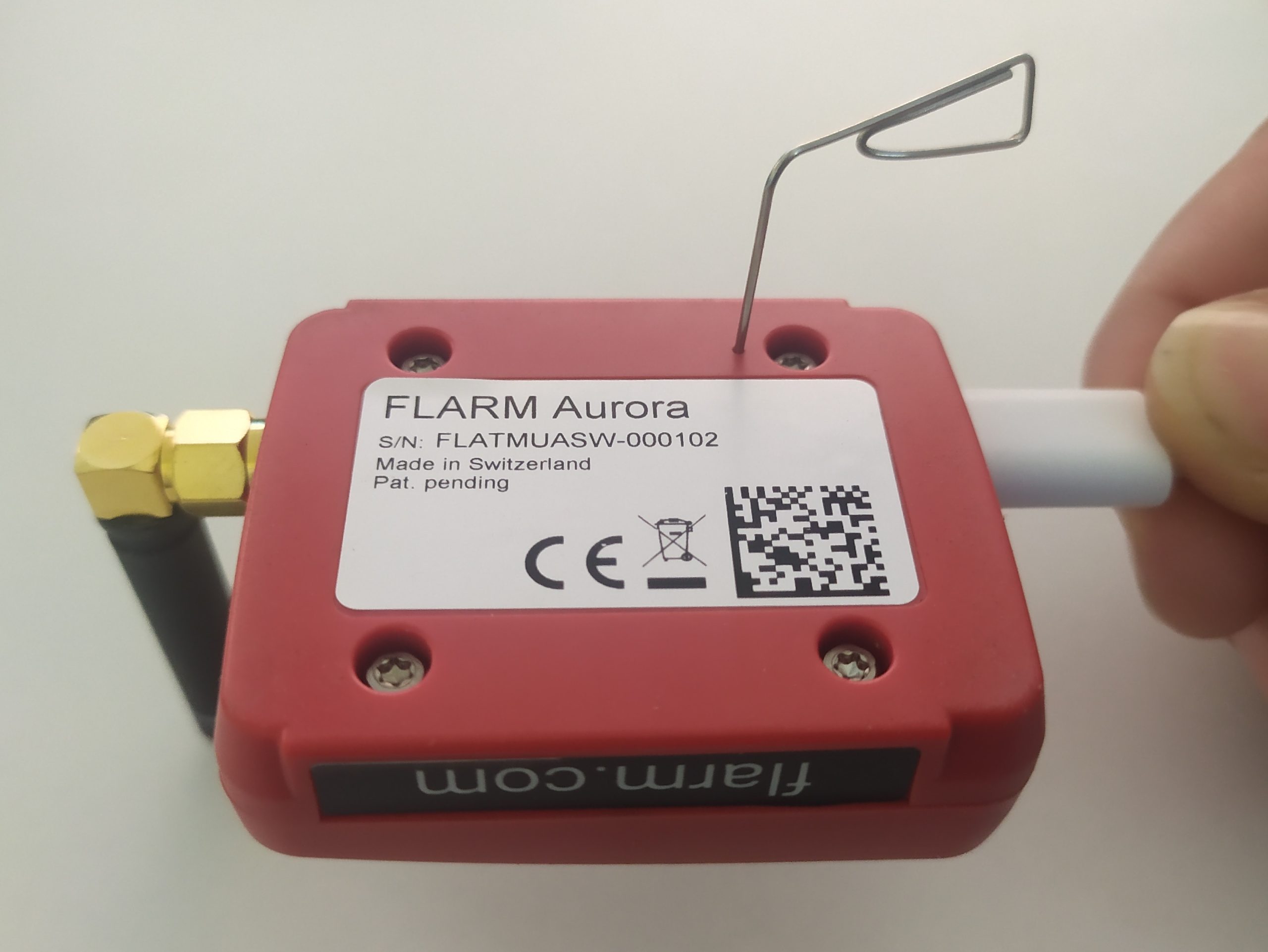
- How do I perform a factory reset on Aurora?
Aurora can be reset to factory settings with the following steps:
- Unplug the device
- Gently insert a paper clip into the hole, push down until you feel a soft click.
- Plug in the device with the paper clip pushed down, wait ~4 seconds
- Unplug the device and plug it back in
The device is now back to the factory settings.
- How do I connect to Aurora via Wi-Fi?
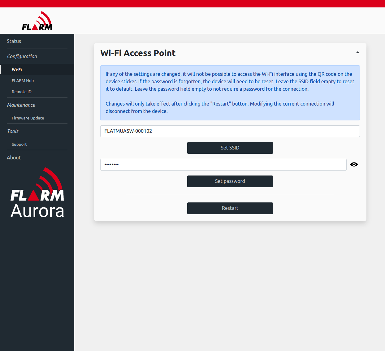
Connect via Wi-Fi to the device using SSID (network name) FLATMUASW-00XXXX (the XXXX is the serial number of the device. The whole text is written on the bottom of the device). The default Wi-Fi password is ‚password‘. Open a browser (such as Firefox, Google Chrome or Microsoft Edge) and navigate to ‚http://10.10.10.10‘. Then the Aurora website (FLARM Hub) is shown.
It is recommended to change the password under ‚Configuration‘->’Wi-Fi‘. Make sure to write down the new password somewhere safe.
- How do I configure Aurora?
Aurora is working right out of the box and does not need much configuration. We do recommend though to change the default password for the Wi-Fi interface.
In order to configure the Wi-Fi interface, or upload new firmware files, you can conveniently use FLARM Hub. This article explains how to connect to it: How do I connect to Aurora via Wi-Fi?
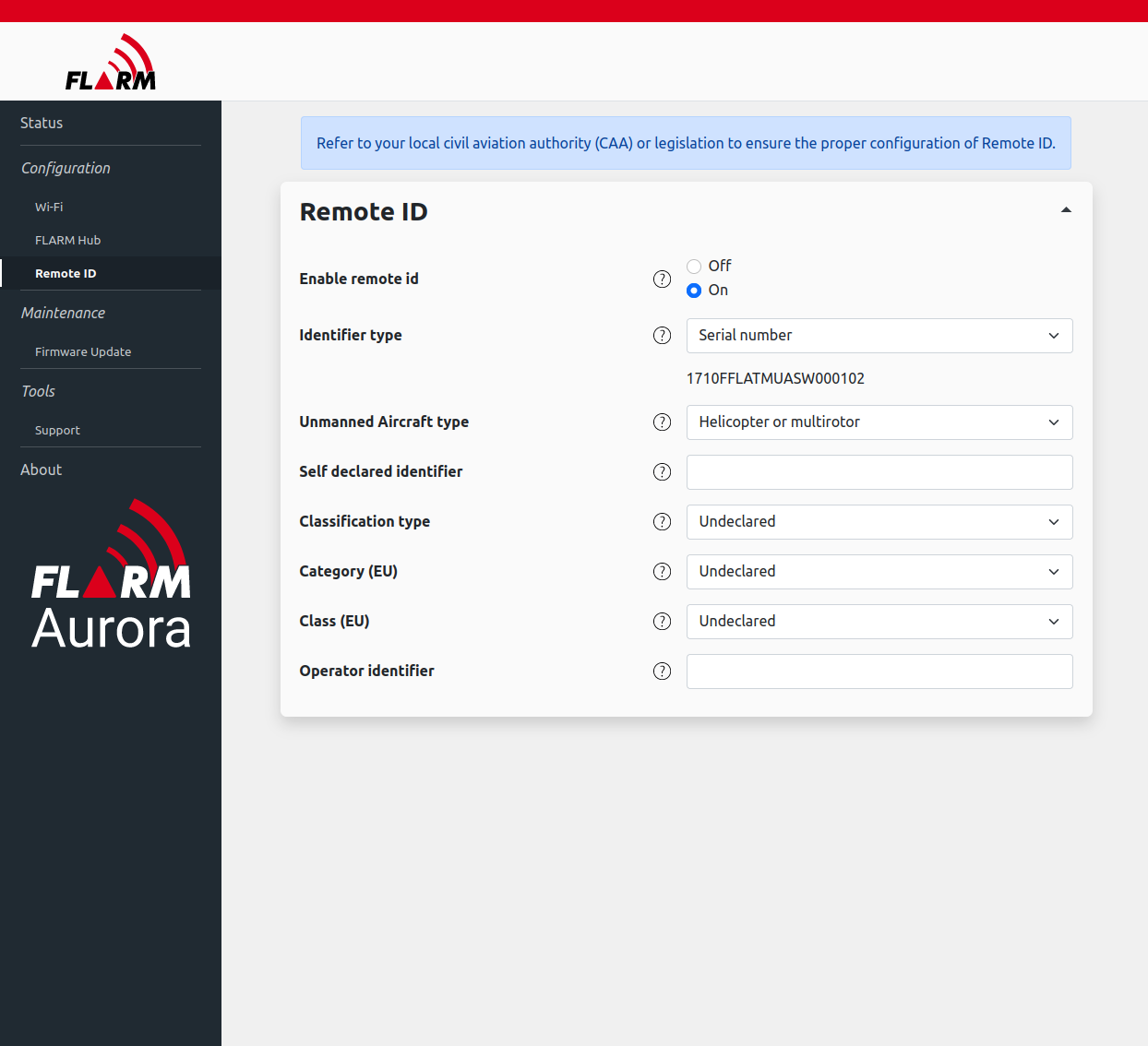
- How do I configure eID / Remote ID
By default, Remote ID is activated with minimal configuration. In order to fully configure it, please use the Wi-Fi interface.
Connect to the device via Wi-Fi: How do I connect to Aurora via Wi-Fi?
Navigate to ‚Configuration‘->’RemoteID‘. Detailed settings can be configured there, as well as RemoteID can be deactivated.
- What is the second connector on Aurora?
Aurora supports two methods of supplying power. One is through the USB-C connector, where you must supply regulated 5 V DC. The other one is through the JST GH connector which accepts a DC voltage in between 5 V and 28 V. This connector is common in many UAV platforms such as Pixhawk.
The pin out is as follows:
Pin Use 1 5-28 V DC 2 Do not connect 3 Do not connect 4 Do not connect 5 Do not connect 6 Ground (0 V) This is particularly useful for applications where no USB-C port is available or you don’t have a 5VDC regulated supply available.
- My UAV refuses to take off with Aurora attached
It is possible that FLARM Aurora covers sensors crucial for the operation of the UAV. Please check that no sensors are covered by the clip and/or device, and if necessary, move the clip to a different position. In particular, the UAV’s GPS antenna may be embedded in the fuselage and might be blocked due to Aurora.
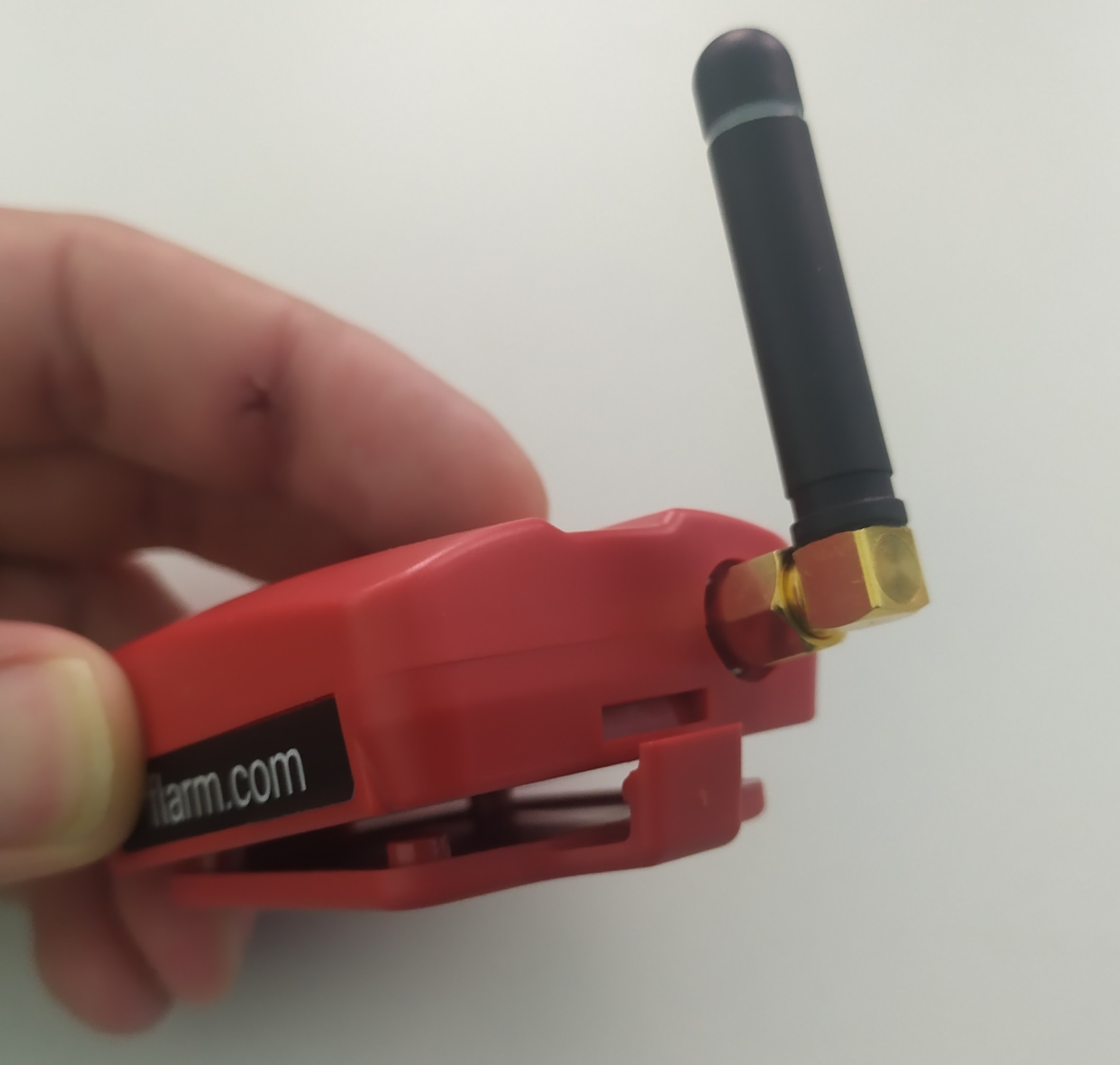
- Can I use another antenna?
Yes, Aurora uses an SMA-RP (Reverse Polarity) connector to allow for other external antennas.
For example, when no good position for Aurora can be found, the external antenna can be placed at a different position.
Make sure to use an 868 MHz (Europe) / 915 MHz (US) antenna with an SMA-RP connector, e.g.
https://www.digikey.ch/en/products/detail/linx-technologies-inc/ANT-868-MHW-SMA-S/11570479 or
https://www.distrelec.ch/en/ism-dsrc-hinged-external-antenna-dbi-male-sma-rp-196mm-screw-molex-2161960011/p/30238354with a suitable adapter, e.g.
https://www.digikey.ch/en/products/detail/linx-technologies-inc/ADP-RPSM-SMAF-G/9826664Please make sure that the device itself has a good sky view for good reception with the internal GPS antenna.
Operating Aurora
- What is FLARM Hub?
FLARM Hub is the web interface to your FLARM device for easy configuration and firmware updates.
You can connect via Wi-Fi: How do I connect to Aurora via Wi-Fi?
In the browser, the status page is loaded:
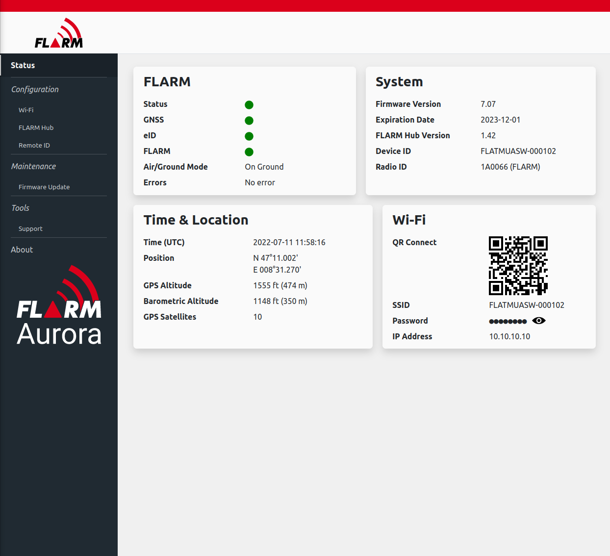
If you changed your Wi-Fi password, you can connect your phone with the QR code in the ‚Wi-Fi‘ box.
The Wi-Fi password can be changed in the ‚Configuration‘->’Wi-Fi‘ page:
The detailed configuration of RemoteID, such as the declared classification type, category or class can be set under ‚Configuration‘->’Remote ID‘.
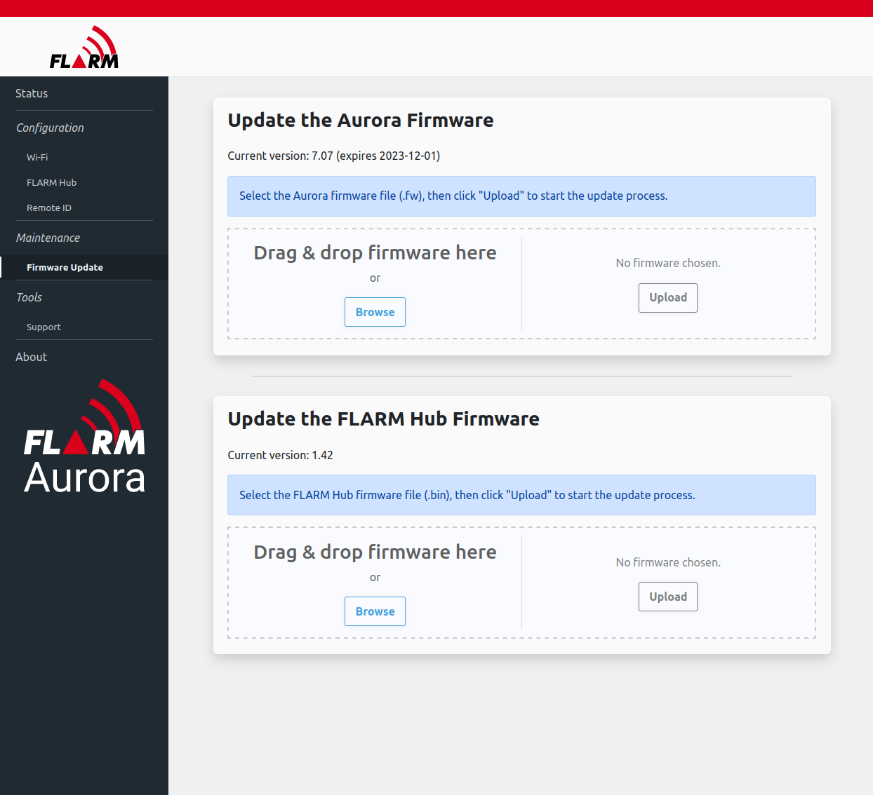
The firmware can be updated under ‚Maintenance‘->’Firmware Update‘. Make sure to update the Aurora firmware annually. The FLARM Hub firmware can be updated to use new features.
In order to create a support package in case of problems with the device, you can go to ‚Tools‘->’Support‘.
The support package includes internal log files and facilitates troubleshooting of the device.
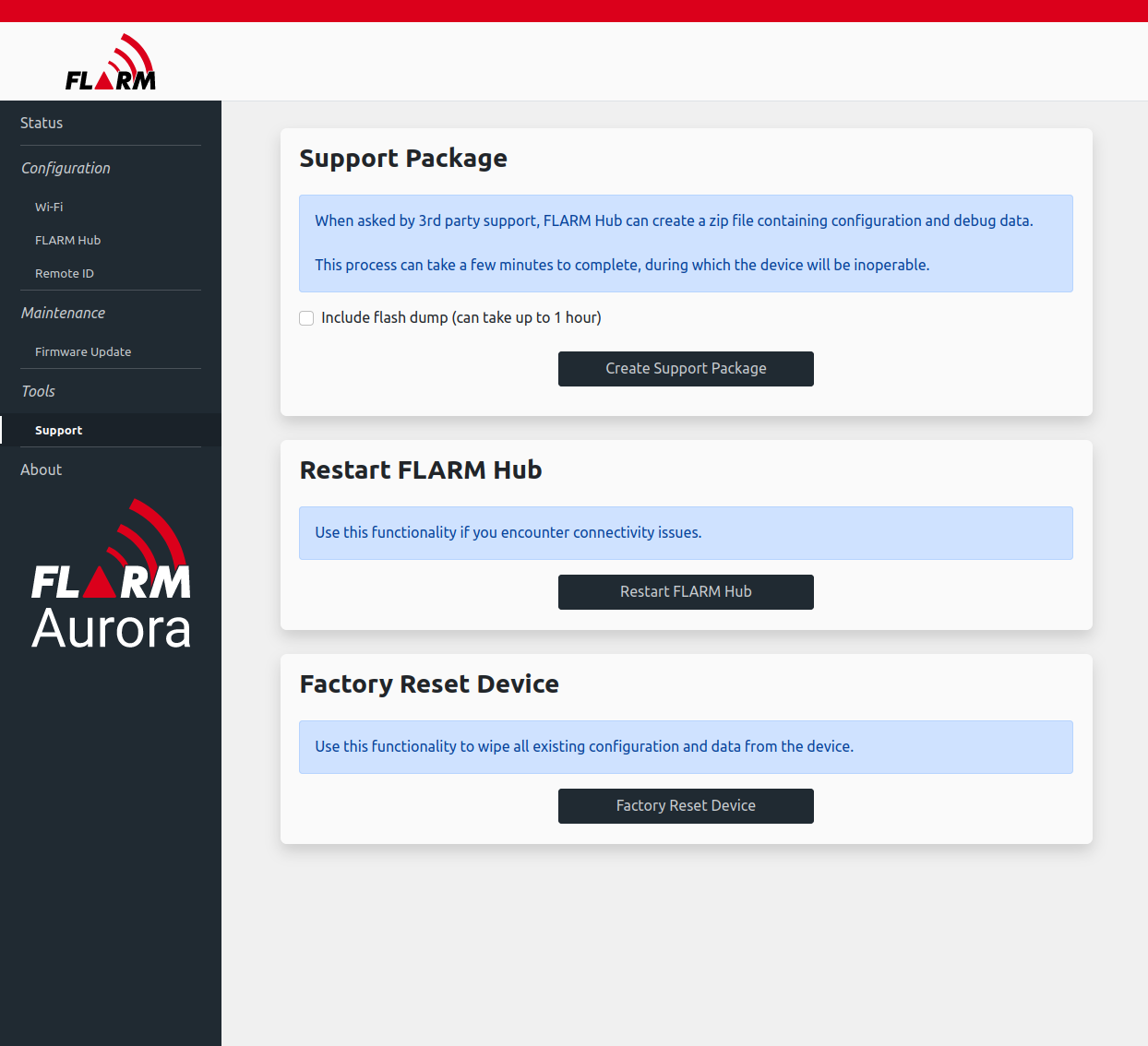
Including the flash download can take a very long time and is generally not required. Only do so when asked by FLARM.
- My Aurora does not work. What can I do?
Make sure the device is correctly connected to power, and that the latest firmware is installed (see Why does the ‚ON‘ light stay red/orange?).
For proper function, the device needs good GPS reception and must be operated outside with good view of the sky.
Try a factory reset: How do I perform a factory reset on Aurora?
If the problem still persists, connect to the Wi-Fi (if possible): How do I connect to Aurora via Wi-Fi?
Under ‚Tools‘->’Support‘, create a support package and send it to ‚info@flarm.com‘ with a detailed description of what is wrong with the device, and that support package.
- Why does the ‚ON‘ light stay red/orange?
This is most probably due to expiration of the firmware.
Please download the newest firmware from https://flarm.com/en/support/downloads/ (look for Aurora).
Connect to the device via Wi-Fi: How do I connect to Aurora via Wi-Fi?
The downloaded file can be uploaded under ‚Maintenance‘->’Firmware Update‘. Please note that there are two firmware files. The one that expires is the ‚Aurora Firmware‘, which is a file that ends with ‚.fw‘. The other is the Hub firmware, which contains the Wi-Fi firmware, including the website and RemoteID functionality.
- How do I mount Aurora using the clip?
Aurora comes with a removable clip to facilitate the use of the device on different aircraft. The clip is designed to be mechanically sufficiently tight to not come loose accidentally during flight. You can install the clip to the UAV using the double-sided tape included in the packaging, or any other suitable method.
The clip is not symmetric: You must insert Aurora in the right orientation. Start with inserting Aurora on the side with the wider flange first, and then push the side with the narrow flange.
In order to remove, push the narrow flange of the clip away from the device, and lift the device off.
- Can I design my own clip for Aurora?